We tested our AX-12A library and motor driver circuit using one of the motors attached to our platform. We quickly realized that the servos on the platform can’t be driven independently of each other; in most cases, all six motors have to move simultaneously in order to achieve any desired position or pose.
This is a video showing how all the motors are affected when we drive only one motor up and down:
Before we started sending signals to all the servos, we figured it would be worthwhile to get familiar with the mathematics of the Stewart Platform.
Unlike articulated robotic arms, the Stewart Platform’s inverse kinematics are simpler than its forward kinematics. What this means is that it’s easier to calculate the leg lengths and motor parameters given a desired position for the platform, than to calculate where the platform is located for a given set of motor parameters. This is fine; we really want the inverse kinematics anyway, and that way we avoid solving a system of 18 non-linear equations with 40 possible solutions.
Some of the papers that we found were not specific to servo-based Stewart Platforms; they simply described the math based on desired leg lengths, and sometimes assumed that linear actuators would be used. This is the case for this paper, which describes a very specific Stewart Platform and focuses on its forward kinematics.
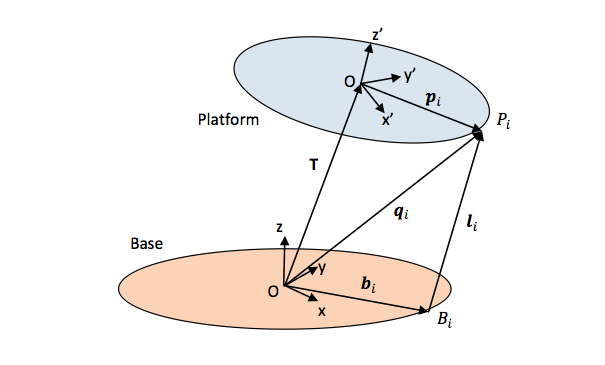
We also found two papers that were more specific for servos. This paper by Filip Szufnarowski describes the inverse kinematic problem very nicely, but it was this document by an unknown author from the Wokingham U3A Math Group that had the most detail and cleanest notation. For example, this image that labels all the relevant points of a Stewart Platform with their corresponding coordinate system:
The inverse kinematics problem of a Stewart Platform can be broken up into two stages:
(1) Given a desired position and orientation for the platform, how far is each joint on the platform from its corresponding base joint,
and
(2) What servo angles, if any, put each platform joint in the positions calculated in the previous step.
The first problem is easy to solve; once you have the appropriate points and coordinate systems defined like in the above image, the distances between base joints and platforms joints can be calculated with simple matrix operations for rotation and translation.
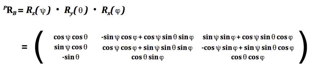
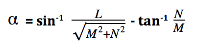
Namely, the length of each leg is calculated as:
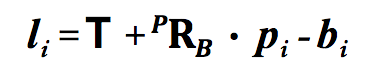
with:
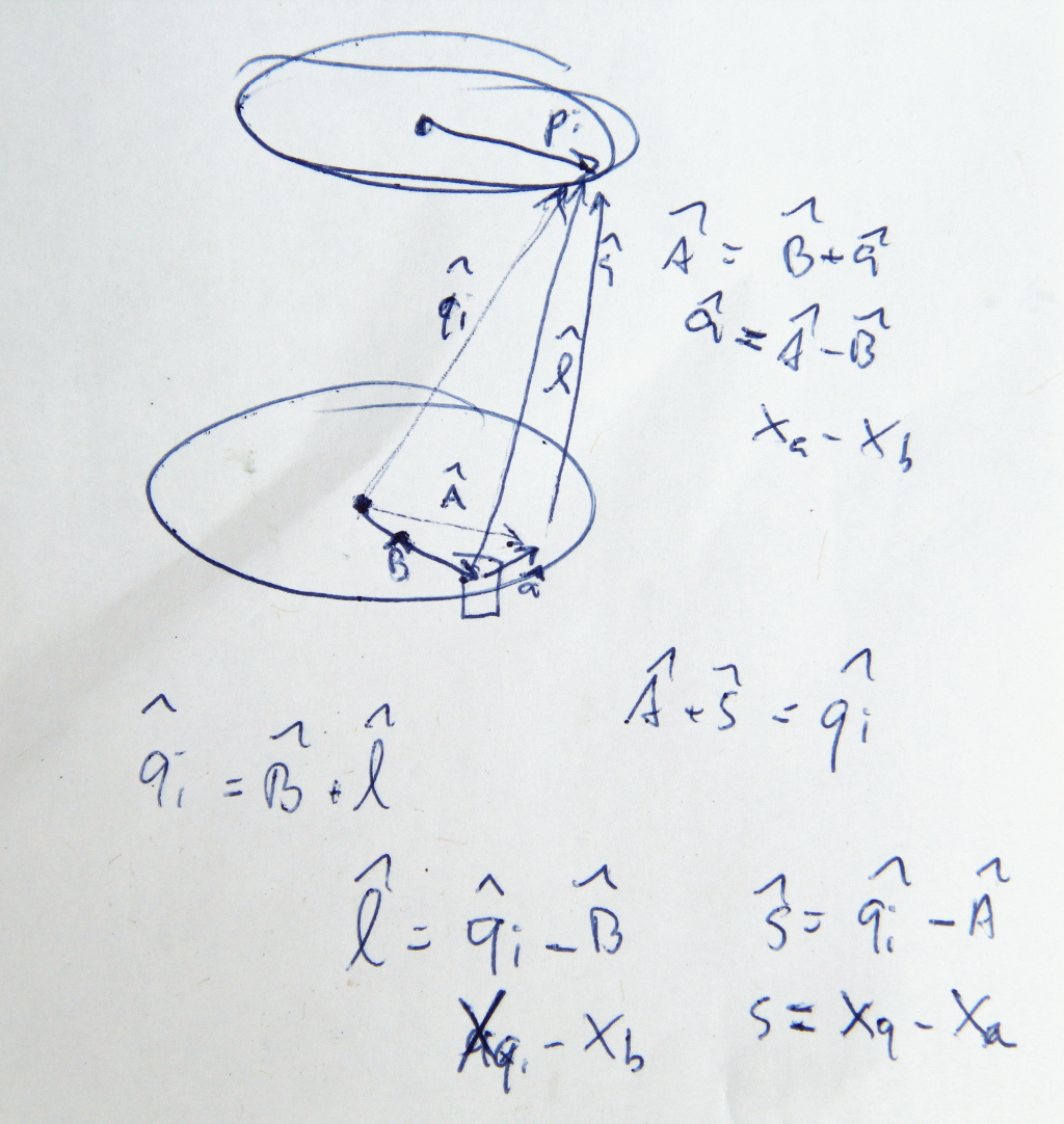
The second part, is a little bit trickier. For each servo, given a platform joint position P, relative to the base joint position B, and fixed lengths for the servo horn a and support leg s, what is the servo arm angle that satisfies the distance l calculated in the previous step.

Since l increases as you vary the servo arm angle from -90° to +90° (relative to base plane), one way to solve for this angle is to do a binary search over the angle values, and find the one that more closely satisfies all the distance constraints. This is done on the code for this Stewart Platform.
But, the Wokingham U3A Math Group document actually steps through the derivation of a closed-form expression for this angle, using some pretty sweet geometry, algebra and trigonometry tricks.
SPOILER ALERT !!! SPOILER ALERT !!! SPOILER ALERT !!! SPOILER ALERT !!!
We actually found a small bug in this part of the document. In equations (8), while calculating l2 and s2, instead of using the (xp, yp, zp) values for the platform joint positions in the platform coordinate system, you have to use the (xq, yq, zq) values, which are relative to the base coordinate system.
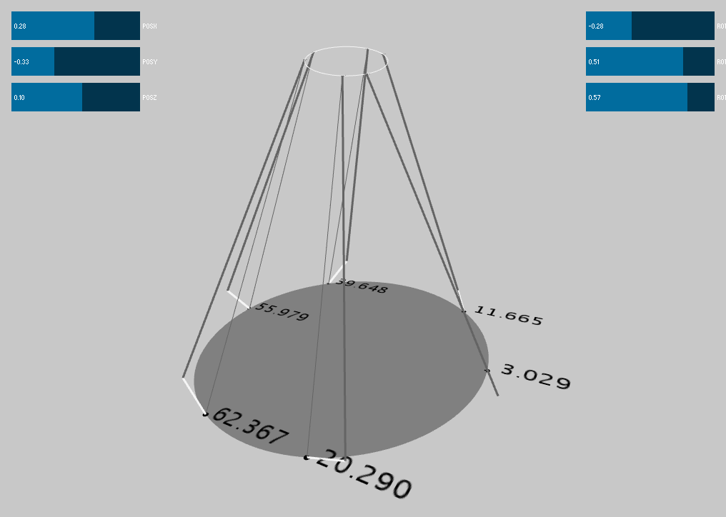
We wrote a simple Stewart Platform simulator for our platform, to see the range of movements that it will be able to achieve, and to double-check the math. The code is in Processing, and is on github.